Scroll down for some photos of the SDR hardware.
Receiver Links
HF SDR: http://sdr.gb0snb.com:8073 (status of the HF SDR)
VHF SDR: http://vhfsdr.gb0snb.com:8074 (status of the VHF SDR)
This line should display the update time of the above information.
HF Receiver
- HF SDR: http://sdr.gb0snb.com:8073
The HF receiver is a KiwiSDR coupled with a wide-band WellGood Loop receiving antenna. It covers from ~5 kHz to 32 MHz.
VHF-SHF Receiver
- VHF SDR: http://vhfsdr.gb0snb.com:8074
The VHF, UHF and SHF receivers, commonly just the VHF SDR, is a custom made RF front end with helical bandpass filtering for each amateur band listed below. A low-noise front end preamp (based around the MiniCircuits PGA-103+) is employed which does its best to recover weaker signals. Helical filtering tries to keep out-of-band strong signals (of which there are many) from causing issues with the five RTL-SDR V3 dongles used on each band. The antenna is currently a Diamond V2000A at 45m above ground (~135m above sea). The bands and frequencies covered are listed below; bands marked with an asterisk (*) may later be configured to have switchable segments within the band.
- 6m (50 – 52 MHz)
- 4m (70 – 72 MHz)
- 2m (144 – 146 MHz)
- 70cm (432 – 434 MHz filtered)
- W70cm (430 – 440 MHz wideband)
- 23cm (1296 – 1298 MHz)*
Bands are run simultaneously so any changes you make do not affect other users.
Photos of the SDRs
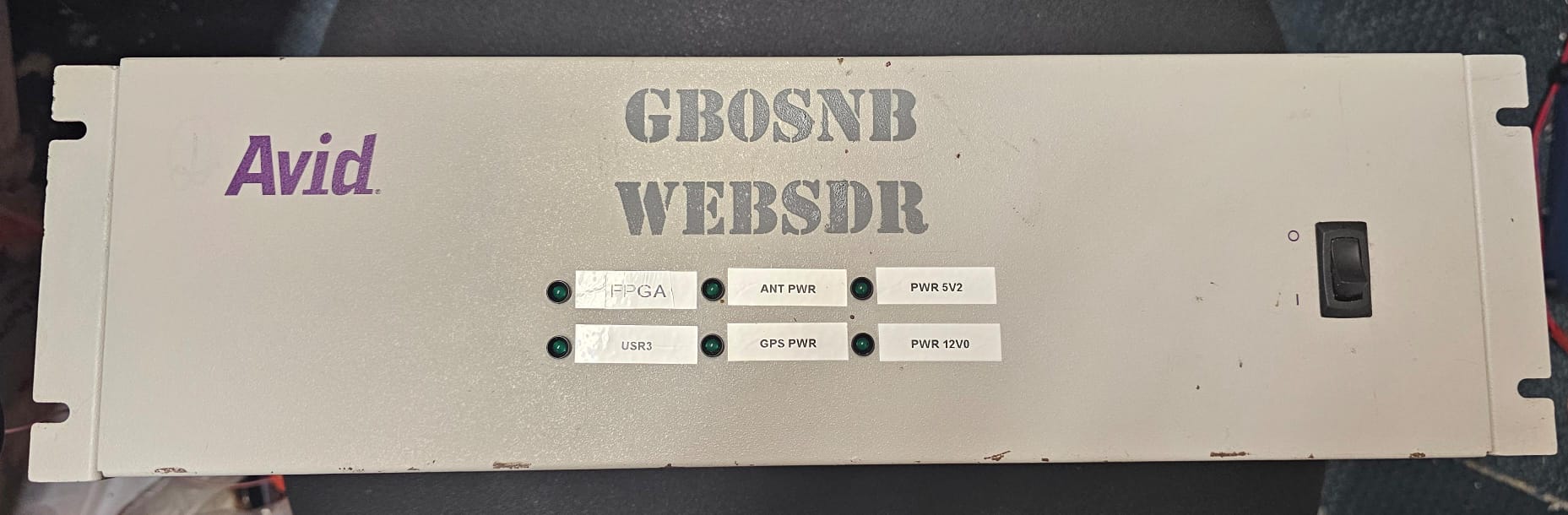
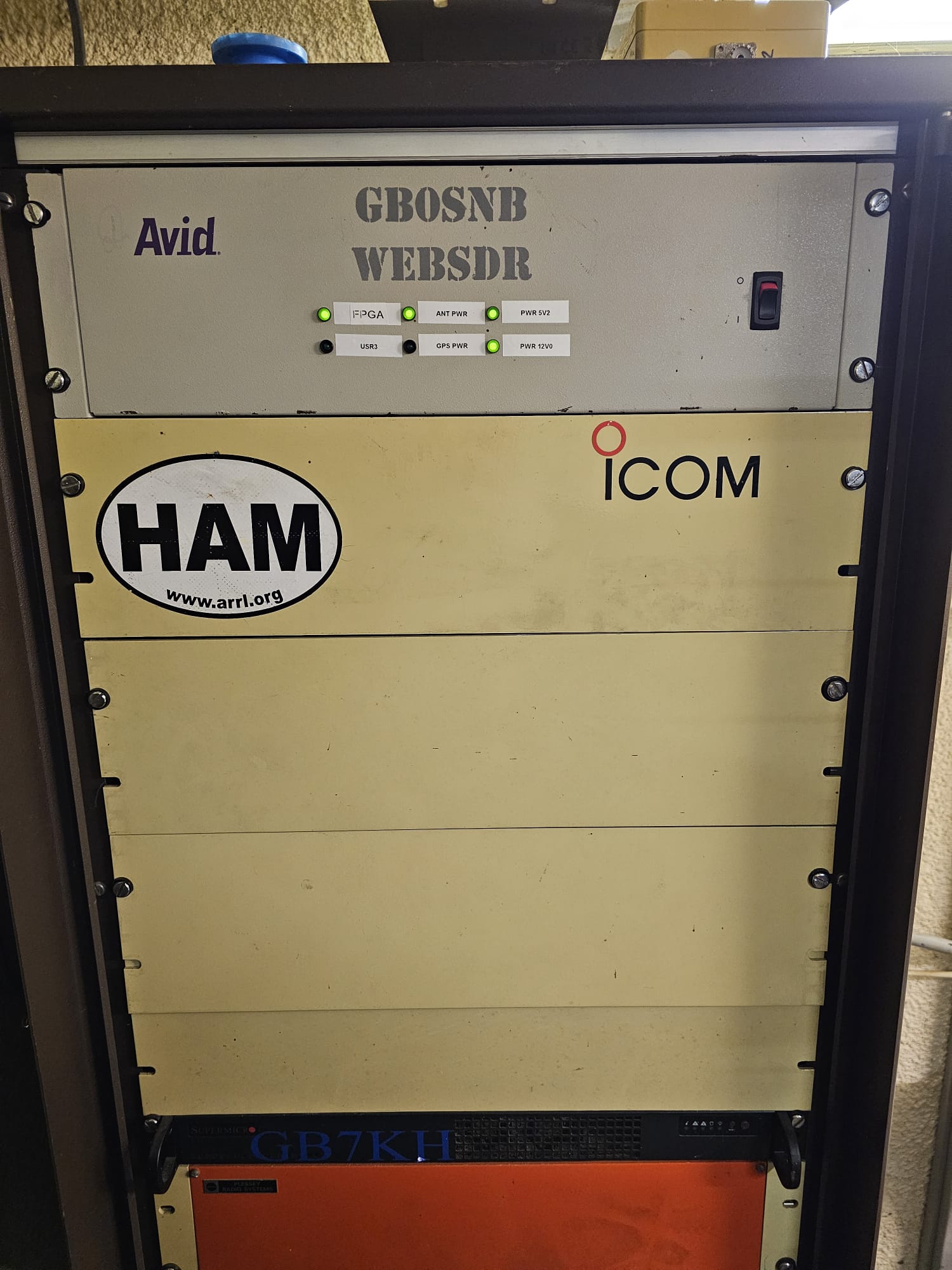
Below is a picture of the HF SDR chassis in the equipment rack.
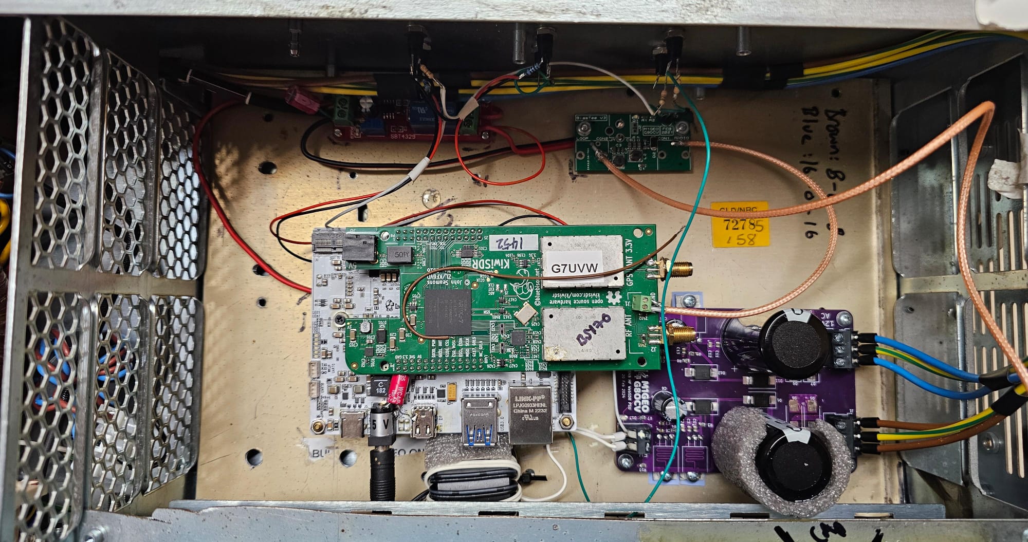
Below is a picture of the HF SDR enclosure, featuring the KiwiSDR, homebrew PSU PCB, antenna control relays, antenna power bias-tee and other associated parts.
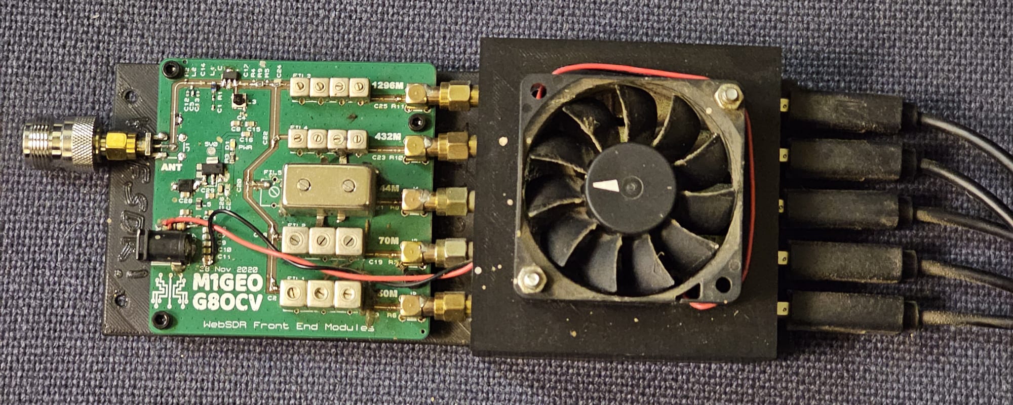
The VHF SDR photo can be seen below. The left PCB is the front-end board with a low noise amplifier, power splitter, and helical filters per band. The SDR receiver modules are under the cooling fan. On top of the cooling fan is a vast amount of dust!
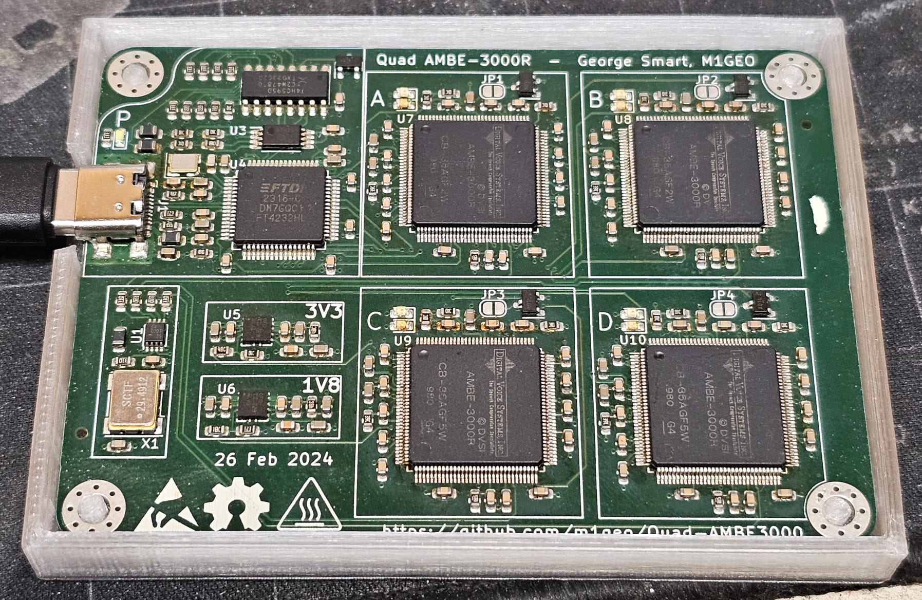
To enable the decoding of digital modes based on the DVSI AMBE Codec, a custom quad AMBE-3000R PCB has been created that enables up to 4 separate concurrent DMR, D-Star, YSF, NXDN, P25 receive streams.
Receiver Timeouts
Both the HF and VHF SDRs have a 30 minute timeout. This means that if you do not adjust the receiver within a 30 minute window, you will be disconnected. You can immediately reconnect (assuming nobody has taken your receive slot, if the hardware is full).
The purpose of this is to stop somebody hogging the receiver for days on end. To reset the timeout, you simply need to adjust the receiver session you are using – adjusting any setting will work.
The receiver will direct you to this section if you reach the timeout.